Gmade r1 crab walk mod
19 November 2021
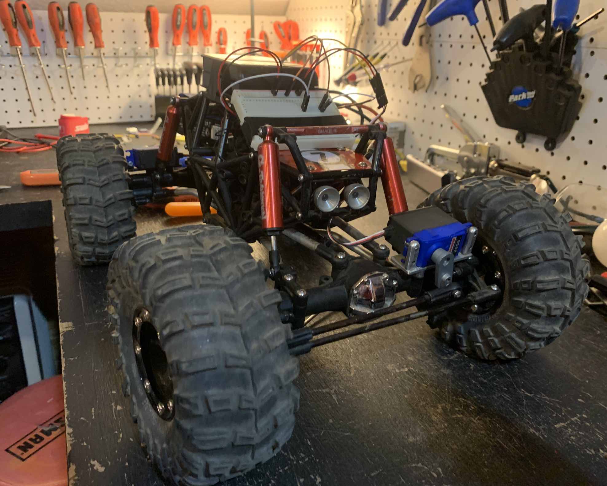
Remote control crawlers (like the gmade r1 I’m using in this project) sometimes offer 4 wheel steering. From what I could find, there is no way to toggle between standard 4 wheel steering, and crab walk steering. Basically… how do you create a toggle to reverse servo direction of just the rear steering? Thats what this does. It uses the switch on a standard traxxas controller to toggle between standard and crab walk.
View the code on github or read on to see more about the hardware involved. I’ll start off by saying I know next to nothing about electricity. My solution is also completely impractical in its current form for actual rc crawling.
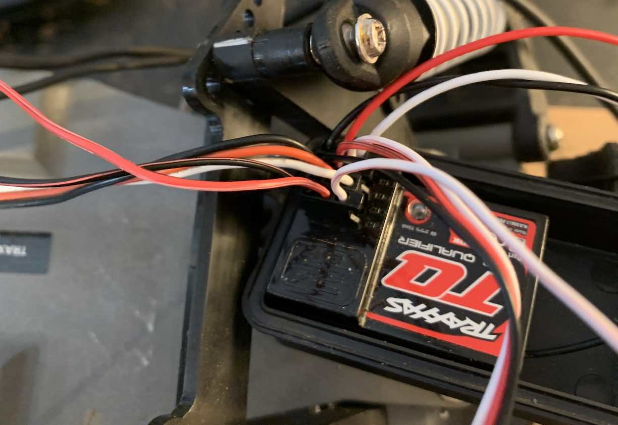
The crux of this problem is reversing a servo with a switch. I’m using the thumb switch on this traxxas remote control. Typical servos like the ones in rc cars are controled use a signal which rapidly turns on, and off, called PWM (pulse width modulaltion). The longer the signal is “on” the wider the pulse width, the shorter the signal is on, the shorter the pulse width. When servos receive a specific pulse width, they move to a specific position. For example, lets say a pulse thats on 20% of the time may have the servo at a 10 degree angle, and when the pulse is on 80% of the time, its rotated all the way to 60 percent. These are just made up numbers… but they illustrate how servos like this work. This PWM signal is typically the white cable, while red and black are there usual positive and negative.
Since 2 of the channels have identical PWM signals affected by the steering, the issue became making them different… or “opposite”. But whats opposite of a 20% PWM signal? 80%? Not always… its dependent on other factors like the “center” “max” and “min” ranges of the servo, what their duty cycle range is. To take all these considerations into account I decided I’d take the route of reading the signal on the receiver (on the car) and then conditionally “reversing” it.
The only hardware I had to work with was a rasperry pi, a breadboard and some wires to testing things without soldering. This is stuff left over from a github integrated desk led setup I built a couple years ago. I struggled to “read” the signal for processing on the pi… there gotta be some piece of hardware that would allow me to get a high quality and accurate signal… I still want to figure that out but for now I just used a software hack of detecting “on” and “off” signals and estimating a pulse width from that. You can actually see the volitility of that estimation in the video. Occasionally you’ll see the back wheels wiggle a little bit.
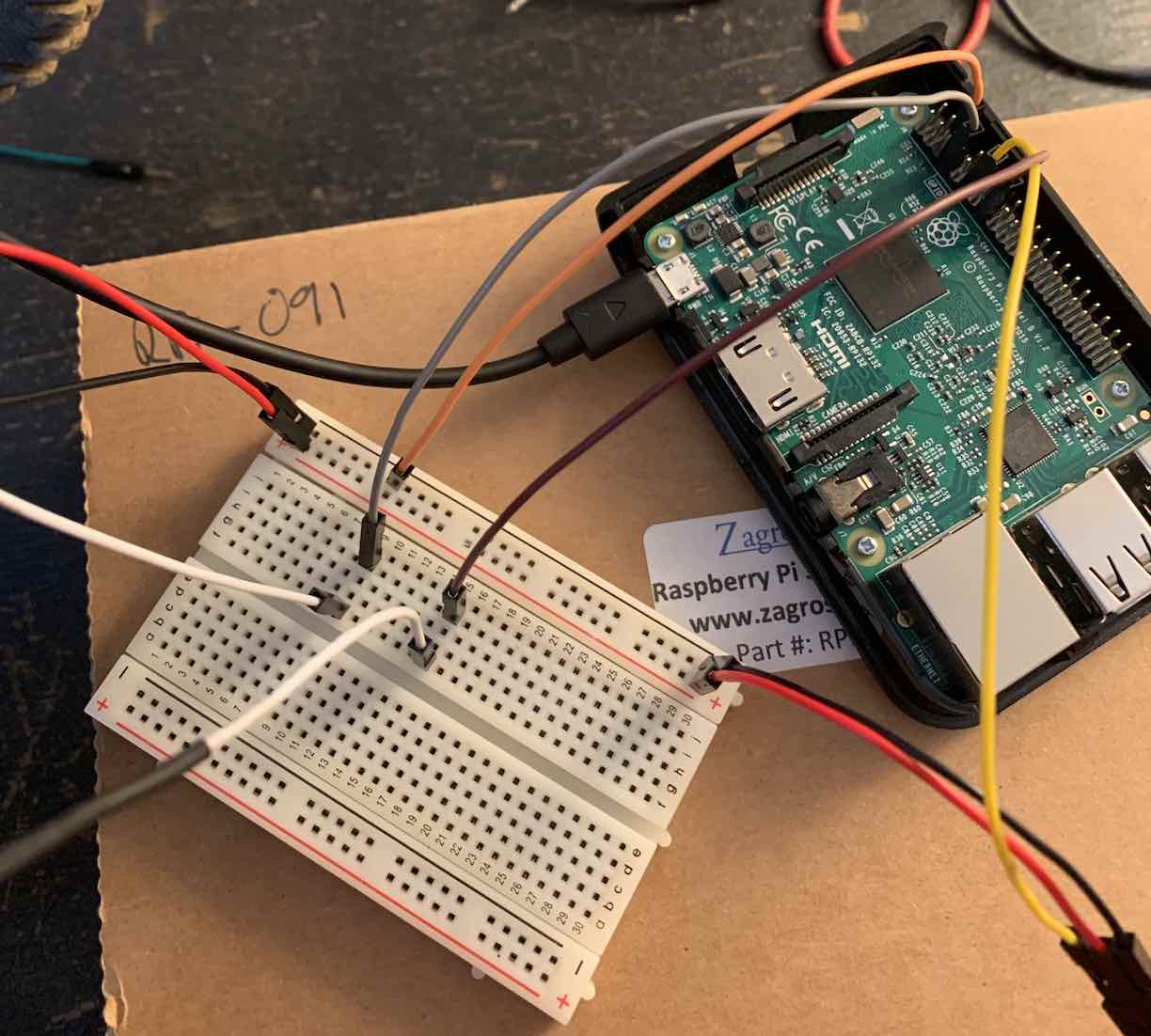
As pictured I also read the thumb switch signal into the pi too so the output signal to the servo could be conditionally reversed. It’s incredibly inneficient to try parsing the PWM signal the software hack way (go figure)… so I only sampled the thumb switch once every second. You can see the side effect of this in the video - after hitting the thumb switch it takes a second for the wheels to reverse. Another reason I gotta figure out the correct (probably hardware?) way to read the signals.
Its rough, but it works. The last bit was unplugging the pi from the outlet to mount it on the car. Luckily, the pi operates off of 5v, which the receiver on the car ouputs to each of its channels. Very convenient. I was able to cut a power cable and splice it onto some servo plugs. Works well enough… no smoke, and no low voltage warnings. Taped everthing to the car and voila.
If you’ve got any info about how to properly read PWM signals into a pi… let me know. Or if there is some obvious hardware solution to reverse a signal like this and remove the need for software all together, even better.